
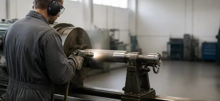
This guide looks at common Thermal Plasma Spray defects and their causes.
A coating may look great when it has been sprayed but fail in service. Many of the causes for coating failures are related to small variations in parameters that have been within specified limits. Often these causes are obvious once they have been pointed out.
Poor Adhesion and Delamination
Perhaps the worst defect of all is that of poor adhesion and resulting delamination. Although a coating may appear to be in good order on visual inspection, it may actually delaminate under application of subsequent loads. Delamination of coating is often a result of a poor pre-treatment surface profile, perhaps a surface that has not been cleaned of oil, moisture or other contaminates prior to coating application. It can also be caused by poor gun to part distance and gun angle, which will result in coatings that ‘splat’ rather than key into the surface. Such coatings will not develop adequate anchor. Check the ‘anchor tooth’ of your blasted surface with a profile gauge and apply within recommended time for the material (usually within an hour or so of blasting).
Porosity and Voids
Porosity or voids within a coating appear to be solid but in fact will allow moisture and corrosive agents to penetrate to the substrate. This type of defect can occur due to inadequate particle velocity or temperature. The particle may not fully flatten on impact or individual particles may not fuse together before they cool. By adjusting the gas flow in conjunction with the standoff distance, it is possible to solve most problems of this nature. Sectioning the coating and viewing under a microscope will confirm the existence of large voids. This is not visible when surface inspecting a coating.
Oxide Inclusions
These defects typically occur as a result of the wire melting in open air before it is propelled onto the part surface. Inevitably, there is a delay in the flight time and during this time oxygen reacts with the hot metal to form a large amount of hard, brittle oxide. This causes the coating to be weak and prone to corrosion. Controlling the shielding gas coverage, setting the arc current and keeping the flight distance as short as possible will all help to reduce the exposure time of the molten wire to air. In order to confirm that the problem is indeed oxide inclusion a metallurgical section through the coating would reveal the oxide as dark stringers between the splats.
Cracking and Spalling
Stress within a coating can build up in many ways. The most common cause is thermal expansion. The coating (which is typically a hard ceramic material) has a different thermal expansion to the substrate it is sprayed onto. As the part is cooled down after spraying, this stress can cause cracking. By allowing the coating to cool down slowly between passes, the stress can be released before it becomes locked into the coating. This can be achieved by spraying in thin layers and allowing adequate cooling time between each layer. Also, selecting a coating/substrate combination with similar thermal expansion characteristics can help to minimise this type of stress.
Uneven Coating Thickness
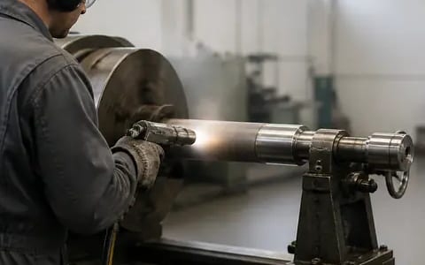
Most variation in coating thickness will arise from inconsistent traverse speed (e.g. by hand or poorly set up robot). Some areas of component geometry are more difficult to coat than others. Parts with corners, apertures, and sections into recesses etc. are notoriously difficult to coat evenly. Generally robot set up to constant speed traverse around component will provide better coating thickness control than manual spraying. Measure coating thickness at a number of randomly selected locations on part and average readings to determine any ‘drift’ prior to part rejection.
Rough or Lumpy Surface Finish
An uneven surface (eg: rough or lumpy) is generally a feedstock problem. This is because the size of the powder particles has a wide distribution, and thus some of the particles will melt completely in the plasma stream, while others will not melt sufficiently to form a smooth surface. Check the feedstock for size before use, and check that the torch settings have been set for the correct powder/wire. It may also be worth checking the flame temperature, and the dwell time of the particles in the plasma stream.
Substrate Overheating or Distortion
Thin parts, which are also heat sensitive, can distort or even loose their temper by excessive local heat input. Such defects are caused by an unbalanced traverse path so that the torch moves to slow in some areas and to fast in others. Delaying the start of spraying for too long also results in an unbalanced heat input. A perfect preheating of the part is crucial, in order to enable an equal and constant heat absorption by the part. For in service monitoring a temperature strip or a thermocouple can be installed in the part, which measures the part temperature during a test spray. Additionally forced cooling by air can be installed between the single layers for thin parts.
Contamination Between Prep and Spraying
The blasted surface can re-oxidise the surface of the part before it is sprayed. Also any contamination on the surface such as fingerprints, oil from handling, or moisture from the atmosphere can also create problems with adhesion. In surface engineering the Thermal Plasma Spray coatings are only as good as the surface they have been bonded to. It is therefore important to ensure that all handling of the part is gloved, a time window is established to complete the spraying within, and that the part is stored in a dry covered area.
The majority of the defects detailed here are caused by small changes in distance, time or cleanliness that have not been detected prior to application or in service. Monitoring and maintaining the “basics” consistently is often sufficient to prevent such problems arising.

Leave a Reply